OK I'm going to go ahead and just lay out what I actually ended up doing. Its up to you to decide if theres anything fundamentally wrong with me.
1) Remove exhaust, install subachad UP/DP, turbo
problems here: got wrong gasket for header-UP. Re-used old one. DP end flange STILL rubbed on my cross member. Tightened everything up as best I could.
other things I did: bought new studs/bolts for header. Removed header. sanded intake flanges until they were shiney and flat. Re-gasketed flanged.
things I had to buy: 2000 OBS Header gasket, 2000 OBS header->cat gasket, 2008 WRX turbo inlet/outlet gaskets, 2xm12 banjo bolts (from dealer, due to feed hole size wierdness. I believe 08 WRX coolant banjo fittings), 1xm10 banjo bolt (from dealer again, no screen, very small hole), the stock td04 oil drain nipple and gasket (dealer), some silicone hose that is size matched, and a NPT threaded hose barb to match that hose, custom made braided line 2ft long with JIS fitting on one side and NPT thread on the other (got at my local hose shop), a 1/8"BPSTxNPT nipple, Some matched size coolant hose with two tees, JISxhose barb fittings (all this from local hose supplier), and clamps.
So what I did here was as follows:
1) removed dummy oil pressure light sender, taped threads of nipple, installed nipple, installed braided oil sending line. Dummy switch is located just underneath the alternator.
2) Cut my TB heater hoses about halfway up, installed tees, did not install third leg of tee yet.
3)Removed cat section of old exhaust, installed subachad UP w/ gasket
4) bolted all the banjo bolts and the oil drain to the turbo, then bolted turbo to UP
5)measured, cut, and installed the third leg of the coolant lines. Feed is on top, return on bottom. Attached other end of oil feed line
6)removed oil pan (this is actually pretty terrible. Look it up online before starting this list), drilled it, tapped it with 7/8" or whatever the threaded side of my oil return nipple was, WASHED IT OUT REAL WELL, let it dry, added make-a-gasket, reattached.
7) plumbed in silicone drain line. I ended up wrapping it in foil tape because it comes pretty close to my exhaust header.

installed Subachad DP. note that the end tri-flange hit my crossmember. I should have just cut it off.
9) Removed the fuel pump relay. Its under the dash on drivers side on a rack of 3 and its green.
10)Cold cranked the engine a bunch of times. This runs the oil & Water pump with no hot exhaust gasses. Apparently its possible to wreck a turbo if you skip this step.
11) Removed C-clip in wastegate actuator and disconnected. Drove it to the exhaust shop. Told guy I wanted 2x bungs, him to move that flange, and a 2.5" pipe with my cheap-o glass pack in there somewhere. Cost ~600 total.
I then proceeded to drive around for about 600 more kms before I got around to installing TMIC and ECU. The WG was propped open and the turbo was not hooked up to the air inlet. Keep in mind that I drove it NOT HARD. this is a good way to overspin your turbo and wreck it. Even with the WG open, it still spins, especially at high rpms.
Next up, I found out the STI intercooler does not fit. After much angry bashing with a hammer, I broke it.
I then bought a 04 WRX intercooler for $40. It fits no problem. I took the plastic Y pipe and cut it at JUST the right angle that a silicone 90 brings everything together real nicely. Lots of hose clamps later, the turbo was plumbed to the engine. At this point I also installed my boost gauge to make sure that the WG being open kept me out of boost. Note: it didnt, but my ECU did not freak out. I think its good to a little over atm. Maybe 4 PSI?
I then drove around for about 400 more kms.
The above was my solution to now having nowhere to put my intake air temperature sensor. I wound up buying a GM open element IAT, cutting a pigtail off a 2007 toyota carolla, getting some washers and O-rings, then drilling and tapping the intercooler as close to the neck as I could. Airflow is non-ideal, but seems to be high enough to keep it cool. The GM PN I think is 12102620 for the pigtail and the sensor is GM #25036751
The washers are just to space it off the core, and there is an O ring on both sides of the washers. I also used thread seal.
http://i2.photobucket.com/albums/y4/knowledge_is_power/Mobile%20Uploads/20140525_120211.jpgWiring:
So I had a bunch of troubles with the ECU.
first was finding a wiring diagram. I went online and downloaded every FSM (factory service manual) I could find. Also any misc "wiring diagram" pdfs I could find. I then compared ECU plug #s (actual # of plugs in the ecu), shapes, sizes, and finally wire colors. I found exactly ONE that worked. Its hosted here:
http://www.filedropper.com/wiringdiagrambut the # (top right corner) is D5M1 in case that goes down.
I then went through my ECU's install manual and decided what sensor info I needed/wanted. I then spent a weekend tracing wiring diagrams with my finger and trying to locate the correct wires in real life, then labeling them. This was surprisingly successful.
tips: If you dont have coil-on-plug ignition, then you have TWO injector drives
Pin#1 on cam and crank sensor is the +'ve signal. the cam signal switches wire color halfway between the engine and the ECU (so it starts out white/orange, then it ends black/white, the black was the white and the white was the orange)
I combined both fans into one assy.
You need to wire the tach in as an output. Theres two wires coming from the Tach/speedo magic box. One passes thru the vehicle speed sensor. This is SPEED. dont worry about it too much, I hooked it into my ECU because why not I dont have any other digital inputs, but if you want you can leave it out, it makes no difference. The wire that does NOT pass thru the speed sensor is the tach feed wire and needs to be an analog output configured as a tach.
I got 18-33g butt crimps, stripped the stupid plastic itshay off em, then used them with proper shrink wrap.
EXCEPT with the cam/crank sensors. I parallel soldered these, then shrunk wrapped em.
with the cam/crank sensors (in fact all shielded wire), it is best to minimize unshielded runs. as such my injectors, ignition, and trigger wires are all super duper short.
power supply is a little tougher than I originally thought. you have to do the following:
1) supply the new ECU with 'on' 14v. NOT acc 14v. and NOT a pin labeled +14v on the ecu. Use the POWER ROUTING DIAGRAM to figure this out.
ACC turns off during cranking. you dont want that. +14v is on ALL THE TIME. you dont want this either.
2) the old ecu actually used to engage the main relay. You need to short circuit this and engage the main relay when key is in ON position. find main relay coil pin, and attach it to the same source you are powering your ecu with.
3)surprisingly, the fuel pump relay coil was not powered by the main relay. This means the fuel pump can be on even though the main relay is off. this seems unsafe and shame on you subaru. I have my fuel pump relay as one of my ecu outputs, which is probably necessary.
I would recommend paying more attention to wire management than I did. Mine is an absolute mess and I dont feel like cleaning it up. I would also recommend wiring in the new harness
while it is unplugged from the new ecu and the battery is disconnected, and then connecting the battery, and then testing all the pins of the new harness to see if it makes sense before finally hooking up new ecu.
I had problems with trigger patterns. Turns out I needed to use the one listed as "EJ251 AVCS" not the one listed as "V5-6 WRX". They are both reluctor. I'm not using any filtering and I get no errors. take from that what you will.
Setting the timing was another challenge when I realized I did not know what subaru's timing mark looked like. Basically how this works is the ECU tells you "ok were gonna try and do 10 degrees before top dead center" then you crank it and look at the marker thing with a timing light (a light that tells you when current is going to spark plug #1) and you make sure the marker is at the -10 spot. if it isnt you enter an "offset" and repeat until it lines up.
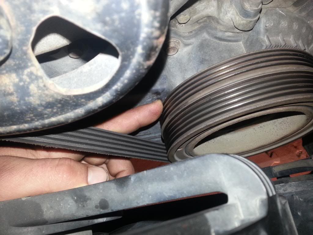
the challenge here is that the timing mark is on the crank pulley and is a tiny tiny divot taken out of the rib closest to the timing cover.
the internet thinks this does not exist. Seriously. Google Subaru timing mark crank pulley and 3 things will come up:
1) how to change the timing belt and the marks on the timing belt
2) the marks on the timing gears and behind the timing gears (neither of which will work)
3)people asking where the mark is, only to be told "subaru engines dont have one, because
you cannot adjust timing in an EFI engine so theres no point"
3)grimmspeed's lightweight crank pulley - I would have given up without this page, as it mentions that the pulley still includes the
OEM timing markHERE! HERE IS A PICTURE TO HELP OTHERS! IT DOES EXIST, IT REALLY DOES. sorry for the hard-to-see-ness of it, my engine will only settle in two positions it seems like.
P.S. I used an offset of 0 degrees.
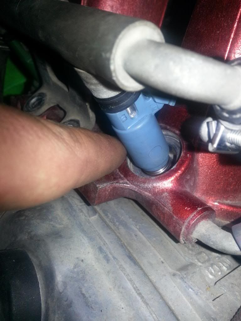
My new problem: I'm running out of injector. And it turns out I (of course) have the super special version of the super special version of subaru injector styles: the WIDE air assist green injectors...